
Cold Room Panel Production Process: 5-Stage Continuous Line and 5-Step Discontinuous Batch Walkthrough
A cold room panel is a metal-skin sandwich with a PU foam core, and its production process is either a five-stage continuous flow — coil decoiling, profiling, foaming, curing in a double-belt press, flying-saw cutting and stacking — or a five-step discontinuous batch cycle where skins are loaded into a hydraulic press, foam is poured, the press closes for cure and opens for de-mold. This how-to walks both processes stage by stage: what happens mechanically, what the operator controls, which process variables set foam density and closed-cell content, what QC checkpoints catch defects, and the six most common defect modes and their root causes. If you are commissioning a new line or debugging an existing one, read this against your process log.
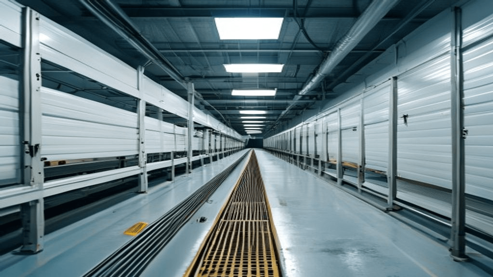
Continuous cold room panel production runs five stages: (1) decoiling and edge profiling of upper and lower steel skins, (2) high-pressure PU foam pouring through a mixing head onto the moving lower skin, (3) 4-8 minute cure inside a 25-35 m double-belt press at 40-50 °C, (4) flying-saw cross-cut to programmable length, (5) panel stacking and film wrapping. Line speed is 6-14 m/min. Discontinuous cycles run five steps per panel: (1) manual or vacuum-lift load of pre-cut top and bottom skins into the mould, (2) close press to target thickness, (3) high-pressure or low-pressure PU shot through pour nozzle, (4) 8-15 minute cure at 45-55 °C platen temperature, (5) press open and de-mold. Critical process variables: foam shot weight to cavity volume (target 5-10% overfill), polyol/isocyanate ratio (index 105-115), platen temperature ±2 °C, chemical temperature ±1 °C at day tank. QC checkpoints: shot weight verification, foam density spot-check, closed-cell content (target ≥ 93 %), dimensional tolerance ±1 mm, skin adhesion peel test. Six common defect modes: voids in corner fill, foam bulge from over-shot, skin delamination, cold-bridge shadow at side rail, density variation across panel face, and post-cure dimensional creep.
A cold room panel is easy to describe and hard to make consistently. The description is a metal-skin sandwich with a PU foam core, foamed to a target density, cured until closed-cell, and cut to length. The production process is where every panel-quality problem in the segment gets set — or prevented — and it is where a first-time factory owner most benefits from walking the line stage by stage before commissioning day. This how-to covers both process paths that dominate 2026 production on a cold room panel machine: the continuous five-stage double-belt line for chain cold-storage and roofing panels, and the discontinuous five-step press-mold cycle for custom cold rooms and modular walk-in units. For each, we walk what happens mechanically, what the operator controls, which process variable is doing the work, and which of the six common defect modes the stage prevents.
Speed-Read — Continuous 5 stages vs Discontinuous 5 steps
| Path | Stage 1 | Stage 2 | Stage 3 | Stage 4 | Stage 5 | Cycle |
|---|---|---|---|---|---|---|
| Continuous | Decoil + profile skins | High-pressure PU pour on lower skin | 4-8 min cure in double-belt press | Flying-saw cross-cut | Stack + wrap | 6-14 m/min continuous |
| Discontinuous | Load pre-cut skins into mould | Close press to target thickness | PU shot through pour nozzle | 8-15 min cure at 45-55 °C | Press open, de-mold | Batch, per press cavity |
Both paths cure PU chemistry the same way — polyol + MDI isocyanate + blowing agent expand, cross-link and close-cell against the two skins. The difference is whether the skins move (continuous) or the press moves (discontinuous), and the whole plant flow follows from that one choice.
Continuous line — the five stages in mechanical detail
Stage 1 · Decoiling and edge profiling
The line starts at two decoilers loaded with pre-painted galvanised steel (PPGI) coils, one for the upper skin and one for the lower. Each coil unwinds under tension into a set of edge-profiling rollers that stamp the tongue-and-groove or camlock or hidden-fix edge shape into the skin's long edges. Skin thickness is typically 0.4-0.6 mm, though some heavy-duty specs run 0.7-0.8 mm; the profiling roller set is dedicated to one skin thickness and one edge profile, so a change requires roll-set replacement. As the skins exit the profiler, they pass through a corona treatment or primer application station that raises the skin's surface energy — this is critical for foam adhesion, and skipping it is the single most common cause of skin delamination at year one. The upper and lower skins then travel on synchronized conveyors toward the foaming station, kept flat by pinch rollers to prevent bowing before foam contact.
Stage 2 · High-pressure PU foam pouring
At the foaming station the two skins are still separated by the target panel thickness (100 mm, 150 mm, 200 mm etc., depending on your line configuration). A high-pressure PU foaming machine has been dosing polyol and isocyanate through a heated line into a mixing head positioned above the moving lower skin. Inside the mixing head, the two chemical streams meet at 100-200 bar impingement — this is the moment the reaction starts. A pour nozzle on the head lays a metered ribbon of unreacted mix across the full width of the lower skin as it moves, at a metered flow rate set by line speed and target foam density. For a 1.2 m wide × 100 mm × 42 kg/m³ panel at 6 m/min, the metered pour rate is approximately 36 kg/min of combined polyol + isocyanate + cyclopentane blowing agent. The chemistry is critical here: polyol temperature at day tank held at 22-25 °C ± 1 °C, isocyanate at 22-25 °C ± 1 °C, blowing-agent content typically 12-14 % of polyol side, and OH:NCO ratio (isocyanate index) held at 105-115. Any temperature drift more than ±2 °C or ratio drift more than ±3 index units shows up as foam density variance panel to panel.
Stage 3 · Cure inside the double-belt press
The two skins with liquid foam between them feed immediately into a double-belt press — a top and bottom heated conveyor belt sandwiching the panel and moving in perfect synchronisation with the line. The belts are heated by thermal fluid at 40-50 °C at the press entrance, warming across the press length to a peak of 55-65 °C in the middle and cooling slightly toward the exit. The panel spends 4 to 8 minutes inside the press — the exact time depends on core thickness and cure profile. During those minutes, the foam expands to fill the cavity, closes off cell walls, cross-links the polyol-isocyanate reaction, and bonds to both skins. Two mechanical controls matter here: belt tension (must be uniform so the panel does not bow or bulge under foam pressure), and belt gap (sets the actual cured panel thickness; typically 1-2 mm less than nominal to account for post-press expansion). If the gap drifts, panel thickness drifts. If the belt heat is uneven, foam density varies across the panel face. The ASTM C518 heat-flow method used to certify the foam's k-factor is measured on cured samples from this stage — if the cure profile is wrong, the k-factor certificate is wrong.
Stage 4 · Flying-saw cross-cut
The cured panel exits the press onto a roller conveyor at line speed. A flying saw — a diamond-tipped or carbide blade mounted on a carriage that accelerates to match line speed, cuts, then decelerates back — cross-cuts the panel to whatever length the order calls for. Length is programmable typically from 2 m to 20 m; the flying saw's minimum practical panel length is set by the cut-to-clear distance, usually about 2 m. Below that, the next cut catches the previous panel before it clears the saw. Cut quality is set by blade condition, cutting speed relative to line speed, and lubrication; a dull or misaligned saw produces skin edge burrs that show up as installation complaints on site.
Stage 5 · Stacking and film wrapping
Cut panels exit the saw onto a stacker — for smaller lines a manual or semi-automatic table, for larger lines a fully automated stacker with vacuum lifters. Panels are stacked with edge protectors and interlayer paper or film to prevent skin-to-skin marking. A polyethylene stretch-film wrapper seals the stack against shipping damage and moisture ingress. This is also where the shipping label with panel spec, batch number and quality mark is applied — traceability that becomes critical if a batch shows a defect after installation.
Discontinuous line — the five steps per panel
Step 1 · Load pre-cut skins into the mould
Unlike continuous, the discontinuous cycle starts with pre-cut skins — sheets of PPGI, stainless, GRP, plywood or aluminium already trimmed to the mould's panel dimensions. An operator (with vacuum lift for large sheets) places the bottom skin into the open press cavity, then the four side profile rails that shape the panel's tongue-and-groove edges, then the top skin. Alignment is critical here — a 2 mm skin misalignment shows up as an out-of-square panel that gets rejected at final QC. On larger presses this loading is 4-8 minutes; on smaller single-mould presses it is 3-5 minutes.
Step 2 · Close press to target thickness
The hydraulic press closes at controlled rate — too fast risks skin damage, too slow wastes cycle time. The press closes to a preset gap that is the target panel thickness (typically 1-2 mm less than nominal to account for post-press dimensional expansion). Once closed, mechanical latches or hydraulic hold pressure keep the platens in position against the foam expansion force, which peaks at 0.5-1.2 bar of internal cavity pressure for a standard PU formulation.
Step 3 · PU shot through pour nozzle
Once the press is closed and locked, the operator triggers the foaming machine's shot cycle. Chemical is delivered through a pour nozzle inserted into a port in the mould's side or top. The shot weight is preset to fill the cavity to 105-110 % of nominal volume — that 5-10 % overfill compensates for foam density gradient and ensures full corner-to-corner fill. Shot weight for a 1.2 × 6 m × 100 mm × 42 kg/m³ panel is about 30 kg total (polyol + isocyanate + cyclopentane). A high-pressure machine delivers this in 8-15 seconds; a low-pressure machine takes 15-30 seconds. The mix reacts on the way into the cavity, expanding as it travels — the geometry of the pour ports matters, and a poorly positioned single pour port produces the "cold-corner" defect where foam did not reach one corner before the reaction ran out.
Step 4 · Cure at 45-55 °C platen temperature
The press platens heat the panel from both sides at 45-55 °C. Cure time depends on foam thickness — 100 mm cores cure in 8 minutes, 150 mm in 11-13 minutes, 200 mm in 14-18 minutes. The cure clock starts when the shot completes and ends when the foam has crossed its gel point and is dimensionally stable. Under-curing produces a soft, dimensionally unstable panel that shrinks over the next 24-72 hours (the "post-cure creep" defect); over-curing wastes cycle time but is not defect-producing at reasonable thicknesses.
Step 5 · Press open and de-mold
The press opens on hydraulic release. Side rails retract or unbolt (depending on mould design). The finished panel is lifted out — for small panels manually, for large panels with vacuum crane. The panel is inspected as it exits: skin condition, edge profile fill, foam density spot-check on a corner, and dimensional check with a straightedge. Panels that pass go to a curing rack for 24 hours of post-press stabilisation before final QC and packaging.
Critical process variables — the numbers the operator controls
| Variable | Target range | Drift shows up as |
|---|---|---|
| Polyol temperature (day tank) | 22-25 °C ± 1 °C | Foam density variance, cell size irregularity |
| Isocyanate temperature | 22-25 °C ± 1 °C | Sluggish reaction, incomplete cure at low temp |
| Isocyanate index (NCO/OH ratio) | 105-115 | Below 100: sticky, wet foam; above 120: brittle foam |
| Shot weight vs cavity volume | 105-110 % overfill | Under-fill: voids; over-fill: press bulge, edge flash |
| Blowing agent content | 12-14 % of polyol side (cyclopentane) | Low: high density, high k-factor; high: shrinkage, cell openness |
| Platen or belt temperature | 45-55 °C continuous, up to 65 °C peak | Density gradient across panel face |
| Cure time | 4-8 min continuous, 8-18 min discontinuous | Under-cure: post-cure creep; over-cure: cycle waste |
Quality control checkpoints on every panel
Well-run lines run five QC checks per production shift:
- Shot weight verification — a check weight on the metering pumps, verified against a standard, once per shift and after any raw-material lot change.
- Foam density spot-check — a 50 × 50 × core-thickness sample cut from the panel edge trim, weighed and measured, once per hour on continuous lines and once every 10 panels on discontinuous.
- Closed-cell content — measured per ISO 4590 or ASTM D6226, on a sample once per shift. Target ≥ 93 %; below 90 % is a QC hold.
- Panel dimensional check — length, width, thickness measured with a calibrated tape on 1 in 20 panels for continuous, every panel for discontinuous. Tolerance ± 1 mm on thickness, ± 3 mm on length.
- Skin adhesion peel test — a strip of skin pulled from the panel edge, measured against a minimum peel force (typically 2 N/mm). Once per shift and after any raw-material lot change.
Panels are marked with batch number, shift, operator and date so that any post-installation defect can be traced back to a specific production window.
Six common defect modes and their root causes
| Defect | What you see | Root cause |
|---|---|---|
| Voids in corner fill | Empty pocket in one corner of panel | Insufficient shot weight; wrong pour port geometry; reaction advanced too fast |
| Foam bulge / edge flash | Foam extrudes past the panel edge | Over-shot weight; press not fully closed; side seal failure |
| Skin delamination | Skin peels away from foam, sometimes at years-in-service | Skin surface not treated (corona/primer skipped); moisture on skin at pour; foam density too low at skin interface |
| Cold-bridge shadow at side rail | Metal-touch line visible on IR scan or condensation on cold face | Side rail geometry does not include a thermal break; foam did not fill fully behind rail |
| Density variation across face | Foam density spot-check varies more than 5 % across panel | Belt or platen temperature drift; pour rate not matched to line speed; mixing head temperature drift |
| Post-cure dimensional creep | Panel measured OK at exit but shrinks in the next 24-72 h | Under-cure; blowing agent gassing out at unfinished cross-link; polyol OH number off-spec |
Certification and standards the process supports
The process described above produces panels that certify to the standards buyers require for construction and cold-storage assemblies. EN 14509 covers self-supporting double-skin metal-faced insulating panels for building applications in Europe; thermal, structural, fire and durability tests all depend on the cure quality and closed-cell content that Stage 3 (continuous) or Step 4 (discontinuous) delivers. FM Global's FM 4880 rates the finished panel for insured-property fire safety. ASTM E84 tests the surface burning characteristics of the finished panel. Foam thermal conductivity — the k-factor buyers compare — is measured under ASTM C518 / ISO 8301 on samples cut from the cured panel; any cure defect in the process shows up as a k-factor deviation on the certificate.
FAQ
How long from press exit to shippable panel?
24 hours minimum. The panel is dimensionally usable at press exit but the foam continues to gas out and dimensionally stabilise for the next day. Shipping earlier risks a customer receiving panels that shrink slightly in transit.
Can the same line make both PU and PIR panels?
Yes, the mechanical line is the same; the difference is polyol and catalyst formulation. Switching from PU to PIR is a raw-material change (change polyol day tank, adjust catalyst level, tune isocyanate index) that takes a shift to purge and re-qualify. Both lines run PIR at slightly higher throughput than PU at the same thickness because PIR reacts faster.
What is the target density spread panel-to-panel?
On a well-run line, ± 2 % across a shift, ± 3 % week-to-week. Anything worse than ± 5 % between panels of the same spec indicates a process control problem — usually temperature drift on the day tank or an out-of-calibration metering pump.
How do I know if the pour rate is right for my line speed?
For continuous: shot rate (kg/min) = line speed (m/min) × panel width (m) × core thickness (m) × target density (kg/m³) × 1.05 to 1.10 for overfill. Below the calculated rate, you get voids; above it, you get bulge and press hydraulic load spikes. On the operator display, this is a single derived number that should be set at start-up and verified at every raw-material lot change.
What is the QC test that catches the most defects the earliest?
The 1-panel-per-hour foam density spot-check. A density measurement is fast (10 minutes for a labelled sample), sensitive to virtually every process drift (temperature, ratio, cure, blowing-agent content), and cheap. Skipping this check is where the "I only found the problem after 200 panels" stories come from.
How does discontinuous cycle time change with core thickness?
Roughly 8 minutes at 100 mm, 11-13 minutes at 150 mm, 14-18 minutes at 200 mm, 20-28 minutes at 250 mm. The scaling is not linear because the cure exotherm helps thicker panels catch up part-way through the cure. On a mould designed for 200 mm as its heaviest spec, running a 100 mm panel at 8-minute cycle is efficient; running a 250 mm panel is not — the press was not sized for it.
For UREXCEED's PU cold room panel production line commissioning, we run FAT to the process controls described above — foam density verification, closed-cell content, dimensional tolerance, skin peel adhesion — with sign-off criteria written into the contract. If you are debugging an existing line's process, our engineering team can travel to your site for process audit and re-qualification. Related engineering deep-dives on the wider cold room panel line stack: Continuous vs Discontinuous PU Sandwich Panel Line explains which of the two process paths above fits your product mix; How to Choose a PU Sandwich Panel Production Line: 12-Point Buyer's Framework is the RFQ scoring checklist; Cold Room Panel Production Line Cost 2026 breaks down the CAPEX and OPEX behind either process choice.
Building a factory? See our production line guide → For a complete plant, browse our cold storage room manufacturing solutions, or contact our engineering team to scope your line.
Ready to plan your refrigeration project?
Share your target output and product mix — our engineering team replies with a capacity plan and quote within three business days.
Get an engineering quoteRelated articles
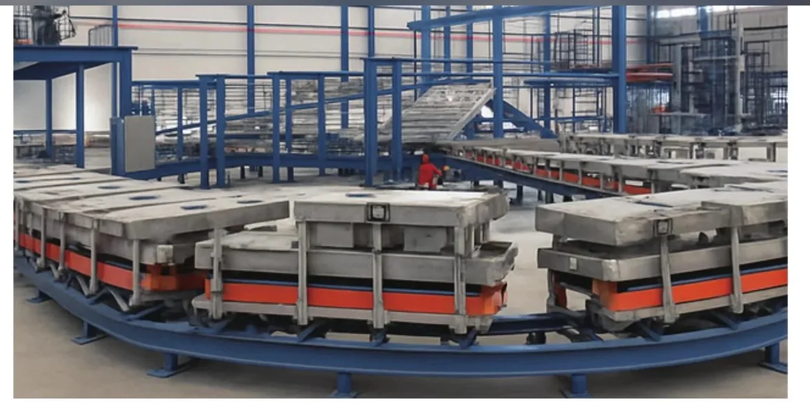
26-Station Ground-Rail Foaming Line Throughput: The Real Math Behind the Numbers
The station count in a foaming line's name is the wrong number to size capacity on. Hourly output is set by takt time and OEE; the 26 stations set curing time and work-in-process. This guide walks the actual throughput math for a closed-loop ground-rail line so you size it against your real production target.
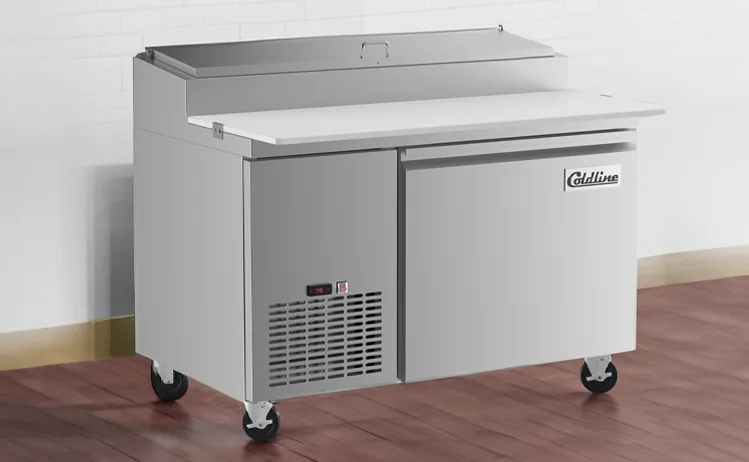
Chef Base PU Foaming, Deep Dive: Why a Load-Bearing Cabinet Is Foamed Differently from a Domestic Fridge
A chef base carries heavy cooking equipment on its top deck, soaks up radiant heat from the cooktop, and is built from two stainless skins — so its PU foam has to be a structural member and an insulator at once. This deep dive walks the engineering that separates chef-base foaming from domestic-cabinet foaming: load-bearing density, k-factor under a hot deck, stainless adhesion, and the defect modes that punish treating the two cabinets the same.

Cigar Humidor Cabinet PU Foam, Deep Dive: Why a Humidity-Holding Cabinet Is Foamed Differently from a Cold-Chain Fridge
A cigar humidor cabinet shares a fridge's two-skin, one-PU-shot construction but not its goal: it holds a narrow 65–72% relative-humidity band at around 18 °C, not a low temperature. This deep dive walks the engineering that makes humidor foaming its own discipline — RH stability, a vapor-tight envelope (ASTM E96 permeance), the condensation a single void causes near saturation, dimensional stability so the door seal stays tight for years, and why it is a precision low-pressure job rather than a high-volume one.