
The Refrigerator Foaming Process, Step by Step: From Liner to Cured Cabinet
Refrigerator foaming is the step that turns a stamped shell and a thermoformed liner into a structural, insulated cabinet. Here is what actually happens inside the jig — mixing ratio, shot, clamp pressure, cure time — and the process variables that decide whether the cabinet comes out void-free or scrapped.

Refrigerator foaming has five stages, in this order. (1) Cabinet assembly: the pre-painted steel outer shell and the thermoformed ABS/HIPS inner liner are joined into a hollow cavity with the door gasket frame and any brackets in place. (2) Jig clamping: the empty cabinet is loaded into a foaming jig or fixture that holds the outer and inner walls at the correct spacing under the pressure the expanding foam will exert. (3) Shot: a high-pressure or low-pressure dispensing machine mixes polyol and isocyanate at a set ratio (commonly around 100:120–140 by weight for rigid PU systems) and injects it into the cavity through one or more ports in seconds. (4) Rise and cure: the liquid mix expands roughly 30-40x in volume, fills the cavity, and cures under clamp for a fixed dwell time — typically several minutes — before the jig can be opened. (5) Demould and stabilize: the cabinet is released from the jig but the foam continues cross-linking and reaches full mechanical strength over hours to days, which is why quality checks (density sampling, void inspection) happen after a stabilization period, not immediately off the jig.
The foaming step is where a refrigerator cabinet gets both its insulation value and its structural rigidity at the same time — which is why a defect introduced here (a void, a density gradient, an under-filled corner) is a defect in the finished product, not something fixed downstream. This walks through what actually happens between "empty shell" and "insulated cabinet," in the order it happens on a real line.
Where foaming sits in cabinet manufacturing
Foaming is the third of four major stages in cabinet production: sheet metal forming and painting of the outer shell, thermoforming of the inner liner, foaming, and final assembly (door, compressor, wiring). By the time a cabinet reaches the foaming station, it is already a sealed hollow shape — outer shell and inner liner joined at the flange, with the door-side frame and any brackets built in — with nothing inside it yet.
Step 1: cabinet assembly before foaming
The outer shell (pre-painted or coated steel, sometimes with a plastic rear panel) and the inner liner (thermoformed ABS or HIPS) are joined so that the space between them forms a continuous, sealed cavity. Getting this cavity geometry right matters more than most buyers assume — see our breakdown of liner thermoforming and its effect on foam fill for how liner tolerance feeds directly into foaming defects. Any gap in this assembly becomes a leak path for foam during the shot, which is one of the most common causes of external flash or internal voids.
Step 2: loading the cabinet into the foaming jig
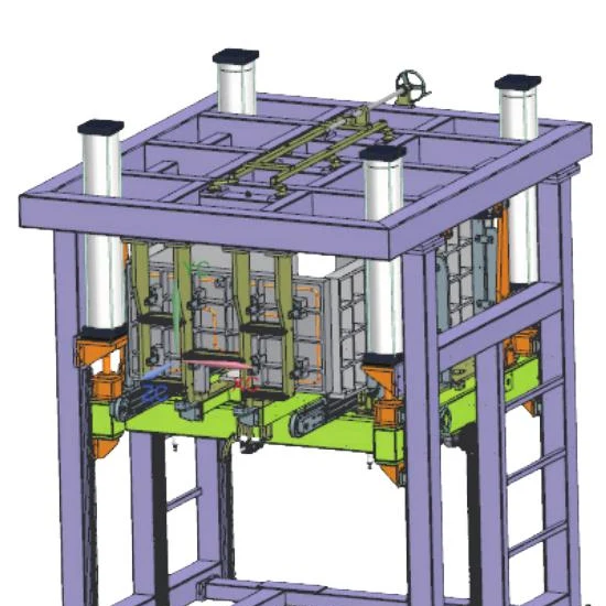
The empty cabinet goes into a foaming jig — a fixture, often multi-station, that clamps the outer shell and inner liner at the correct spacing and holds that spacing against the internal pressure the expanding foam will generate. This clamping step is not optional tooling; it is the single biggest lever on dimensional consistency. A rigid, well-maintained jig holds wall thickness uniform across every cabinet it produces; a worn or under-clamped jig lets the liner bow outward under foam pressure, producing thin spots exactly where insulation performance matters most.
Jig configuration varies with production volume and cabinet type — single-station linear fixtures for lower volumes, rotary multi-station jigs (4-station, 6-station, and up to 16-station crawler lines) for higher throughput, each cycling through load, shot, cure and unload positions continuously.
Step 3: the shot — mixing and injection
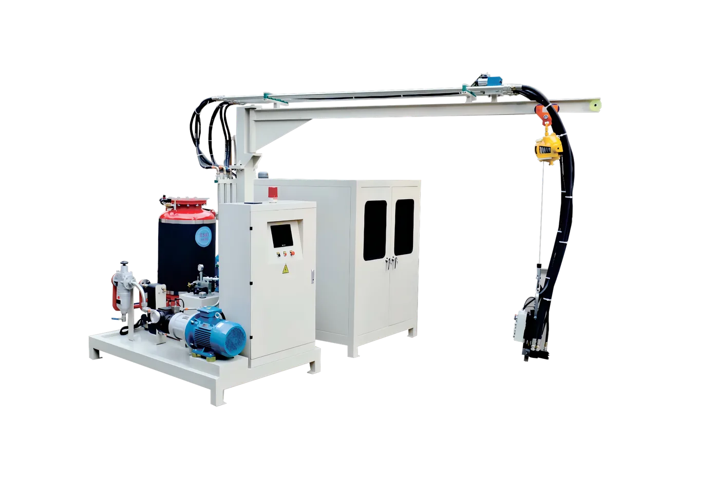
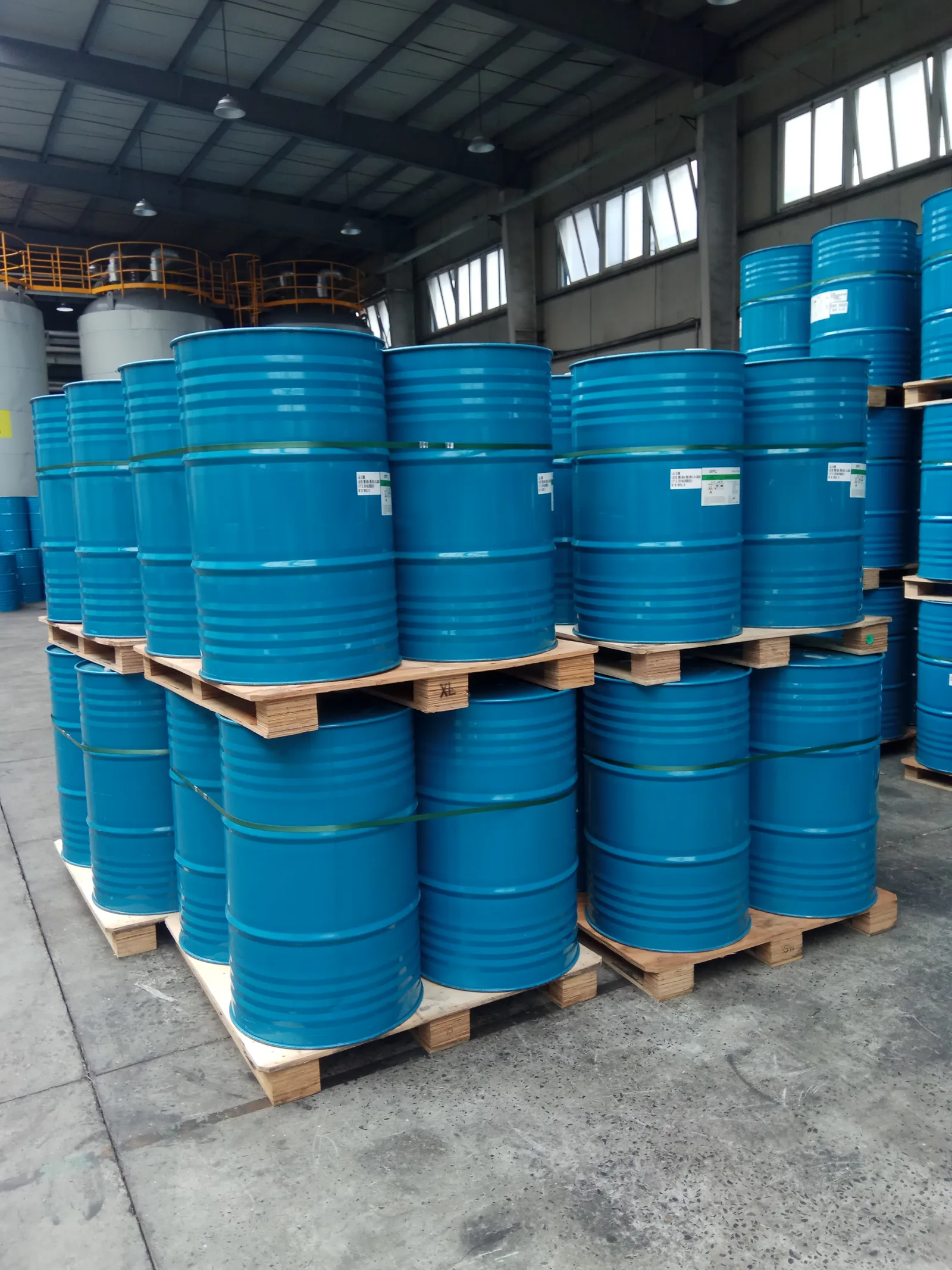
A PU foaming machine meters two liquid components — polyol and isocyanate (MDI) — at a controlled ratio, mixes them at high shear in a mixing head, and injects the mix into the cavity through one or more ports, typically in a few seconds. The two dispensing approaches are:
| Method | How it mixes | Where it fits |
|---|---|---|
| High-pressure | Impingement mixing at 100–200+ bar, self-cleaning mixing head | High-volume cabinet lines, consistent shot-to-shot accuracy |
| Low-pressure | Mechanical stirrer mixing at lower pressure, mixing head needs solvent flushing | Lower-volume runs, simpler machines, more operator-dependent consistency |
We cover the tradeoffs between the two in more depth in high-pressure vs low-pressure PU foaming machines; for the process itself, the key point is that shot weight and mix ratio are set by the machine, not eyeballed, and both are cabinet-specific — a chest freezer cavity and a display cabinet door take different shot profiles even with the same chemistry.
Step 4: rise, fill and cure
Once injected, the liquid mix reacts and expands — a rigid PU system typically expands on the order of 30–40 times its liquid volume — flowing through the cavity to fill every corner before gelling. This is the phase where cavity geometry, jig clamp force and shot placement either combine to give a fully filled, void-free cabinet, or don't. Corners farthest from the injection port, and any narrow ribs or brackets inside the cavity, are the highest-risk fill points, which is why port placement is part of the tooling design, not an afterthought.
The reaction is exothermic — the cabinet warms measurably during cure — and the jig stays clamped for a fixed dwell time, commonly in the range of several minutes depending on cabinet size and formulation, before the foam has gelled enough to hold its shape unsupported.
Step 5: demould and post-cure stabilization
The cabinet comes off the jig once it can hold its own shape, but the polyurethane cross-linking reaction is not finished at that point — mechanical properties and dimensional stability continue developing over hours to a few days after demoulding. This is a practical reason serious quality checks — density sampling by cutting and weighing a coupon, void inspection, dimensional check against the liner — happen after a stabilization period rather than immediately off the jig: testing a cabinet before the foam has finished curing can give a false read on density and strength.
What actually goes wrong, and where in the sequence it starts
Most cabinet-foaming defects trace back to one of these five steps rather than to the chemistry itself:
- Voids and under-fill — usually a Step 4 problem caused by insufficient shot weight, poor port placement, or a cavity geometry issue from Step 1.
- Density gradients — commonly a jig-clamping issue from Step 2: uneven clamp pressure lets the cavity volume vary shot to shot.
- Surface bowing on the liner — a Step 2 problem: the jig isn't holding the liner rigid enough against internal foam pressure.
- Inconsistent shot-to-shot output — a Step 3 machine-calibration issue, more common on low-pressure systems with manual flushing between shots.
We go deeper into diagnosing these specific failure modes, with the sequence above as the reference, in refrigerator cabinet PU foaming defects and troubleshooting.
Why the blowing agent choice matters to this process, not just the finished foam
The blowing agent creates the cell structure during the rise stage in Step 4, and different agents have different reaction profiles — affecting rise time, exotherm and the cure window the jig needs to hold. Cyclopentane is the mainstream cold-chain choice today; regulatory exposure differs by destination market under frameworks like the US EPA's Significant New Alternatives Policy programme, which governs which blowing agents are acceptable for foam applications in the United States. We compare the process and compliance tradeoffs of the main agents in cyclopentane vs HFC-245fa vs HFO blowing agents.
Density itself — the number that determines both insulation performance and structural strength — is verified after cure using standardized methods such as ASTM D1622, the apparent-density test for rigid cellular plastics, which is why density sampling is a post-stabilization step rather than something read off the machine in real time.
Frequently asked questions
What is the refrigerator foaming process?
It is the manufacturing step where liquid polyurethane is injected into the sealed cavity between a refrigerator's outer steel shell and inner plastic liner, then expands and cures into rigid closed-cell foam. The foam both insulates the cabinet and bonds the shell and liner into a single rigid structure, which is why foaming happens after the shell and liner are assembled and clamped in a jig, not as a separate bonding step.
How long does the foam take to cure in a refrigerator cabinet?
The cabinet is held clamped in the jig for a dwell time of several minutes, long enough for the foam to gel and hold its shape unsupported, but the polyurethane cross-linking reaction continues after demoulding — full mechanical and dimensional stability develops over hours to a few days. This is why density and void checks are done after a stabilization period rather than immediately after the cabinet leaves the jig.
What causes voids in refrigerator foam insulation?
Voids are most often caused by insufficient shot weight, poor injection-port placement relative to the farthest corners of the cavity, or a cavity geometry problem introduced during shell-and-liner assembly. Uneven jig clamp pressure is a separate but related cause of density gradients rather than voids specifically. Diagnosing which of these applies requires checking the specific defect location against the shot pattern and jig condition.
What is the difference between high-pressure and low-pressure foaming machines?
High-pressure machines mix polyol and isocyanate by impingement at 100 bar or more through a self-cleaning mixing head, giving more consistent shot-to-shot accuracy at higher volumes. Low-pressure machines mix mechanically at lower pressure and need the mixing head flushed with solvent between shots, which makes consistency more dependent on the operator. The choice is typically driven by production volume rather than cabinet type.
Products Mentioned in This Article
Ready to plan your refrigeration project?
Share your target output and product mix — our engineering team replies with a capacity plan and quote within three business days.
Get an engineering quoteRelated articles
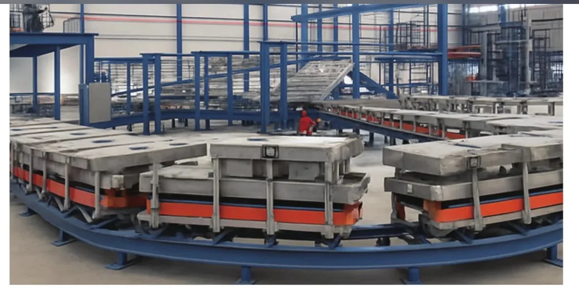
26-Station Ground-Rail Foaming Line Throughput: The Real Math Behind the Numbers
The station count in a foaming line's name is the wrong number to size capacity on. Hourly output is set by takt time and OEE; the 26 stations set curing time and work-in-process. This guide walks the actual throughput math for a closed-loop ground-rail line so you size it against your real production target.
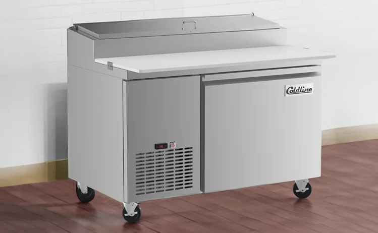
Chef Base PU Foaming, Deep Dive: Why a Load-Bearing Cabinet Is Foamed Differently from a Domestic Fridge
A chef base carries heavy cooking equipment on its top deck, soaks up radiant heat from the cooktop, and is built from two stainless skins — so its PU foam has to be a structural member and an insulator at once. This deep dive walks the engineering that separates chef-base foaming from domestic-cabinet foaming: load-bearing density, k-factor under a hot deck, stainless adhesion, and the defect modes that punish treating the two cabinets the same.

Cigar Humidor Cabinet PU Foam, Deep Dive: Why a Humidity-Holding Cabinet Is Foamed Differently from a Cold-Chain Fridge
A cigar humidor cabinet shares a fridge's two-skin, one-PU-shot construction but not its goal: it holds a narrow 65–72% relative-humidity band at around 18 °C, not a low temperature. This deep dive walks the engineering that makes humidor foaming its own discipline — RH stability, a vapor-tight envelope (ASTM E96 permeance), the condensation a single void causes near saturation, dimensional stability so the door seal stays tight for years, and why it is a precision low-pressure job rather than a high-volume one.